
Project Description
Introduction
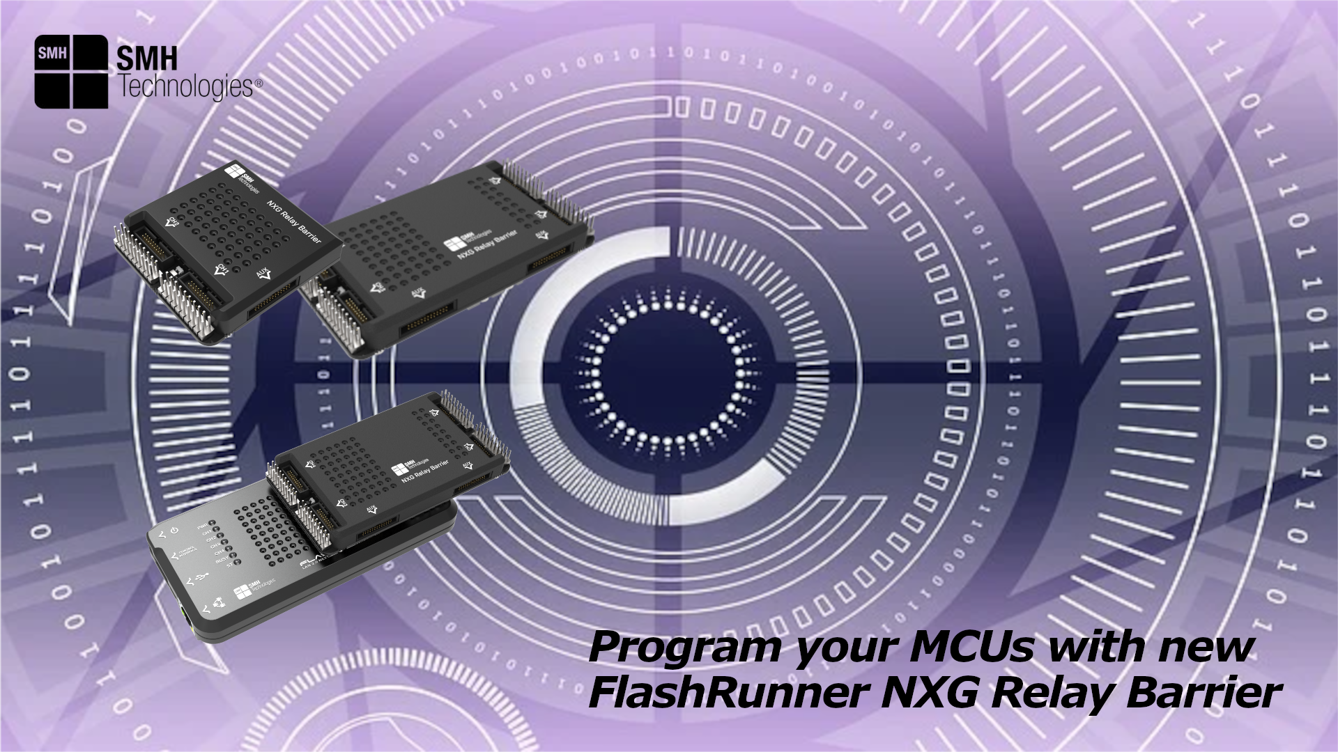
SMH Technologies offers a new useful tool dedicated to FlashRunner 2.0 NXG to provide galvanic isolation between the programming system and the devices under test/programming (DUTs).
Relay Barrier versions
FlashRunner 2.0 NXG supports up to 4 channels so it allows to interface in parallel up to 4 independent and heterogeneous devices. The customers choose to enable the needed channels (1, 2, 3 or 4) according to their project requirements and, eventually, extends the programming system capabilities, in terms of numer of channels, through a simple software license update.
Relay Barrier with Cable Interface is available in two different versions:
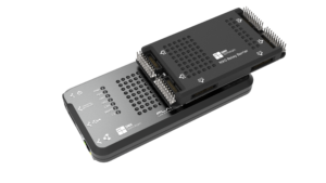
FlashRunner 2.0 NXG Relay Barrier 4-channels
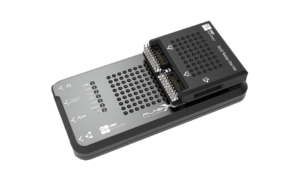
FlashRunner 2.0 NXG Relay Barrier 4-channels
Relay Barrier operation
Relay barrier gives the chance to separate the programmer lines and the ISP programmable devices when other operations such as In-Circuit Test procedures are carried out by the machinery.
Relay Barrier is normally open, separating programmer’s lines and ISP programmable devices but connecting Auxiliary Connector to ISP device connector. Relay command and power supply are provided directly through the FlashRunner 2.0 NXG ISP connectors.
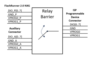
With the command RLYCLOSE (please check FlashRunner 2.0 Programmer’s Manual for more details) the specific channel is activated and the current can flow through the external relay coils closing the relay. The command RLYOPEN stops the current flow releasing the relays.
RLYOPEN command
• the relay switches go in the (normally) OPEN position
• the ISP device connector lines of the barrier are connected to the
auxiliary connector
RLYCLOSE command
• the relay switches go in the CLOSED position
• the ISP device connector lines are connected to the Active Module
lines
Programmer integration (machine side)
When the programmer is placed outside the fixture, SMH provides ways composed by flat cables and mass interconnections to reach the fixture and maintain good singals integrity and stability.
• Recommended flat cable length: 50cm (twisted shielded pair cables)
• Mass interconnection interfaces between machine and fixture: SMH
provides different solutions to achieve this. ODU 4 channles for this
product in particular, but in general VPC 8 channels or pylon block are
also valid alternatives for other types of products and applications.
• Inside the fixture, it is highly suggested to not overcome a length of
30cm to reach the target using twisted shielded pair cables.
• Keep the ISP lines separated from the rest of the cables that a
production system would require for other purposes.
Following these guidelines, it is possible to exploit the programming system at full potential without compromising protocol frequencies or data transfer speeds.

Programmer integration (fixture side)
When the programmer is placed inside the fixture the new relay barrier allows the customer to wrap the wiring instead of soldering it for a better configuration.
• Inside the fixture, it is highly suggested to not overcome a length of
30cm to reach the target using twisted shielded pair cables.
• Keep the ISP lines separated from the rest of the cables that a
production system would require for other purposes.
Following these guidelines, it is possible to exploit the programming system at full potential without compromising protocol frequencies or data transfer speeds.