
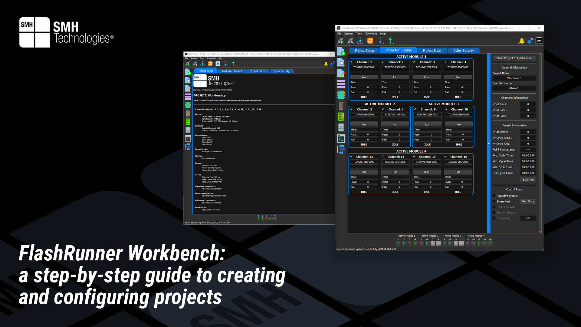
Project Description
The previous technical article provided an overview introducing the FlashRunner Workbench. This text offers a comprehensive guide to the process of creating and configuring a project using the full potential of this technology.
Project creation
Creation of a project in the Workbench is followed by the graphic interface step by step. The user with a maximum of 7 steps will be ready to run the project.
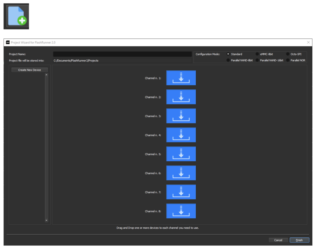
• On the top a name for the project can be inserted.
• On the right-top it can be selected the Configuration Mode which depends on the device you want to program.
• In the center there are the available channels.
• On the left can be created a device’s project.
Device selection page
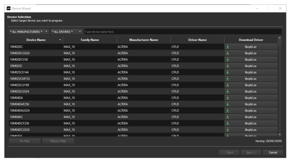
Clicking on “Create New Device“ you can select which target device you want to program. Remember that each device needs its library, written in “Driver Name” column; make sure to have this library. You can download it locally on your PC the latest version by just clicking on the driver on the “Download Driver via FTP” column.
FRB Management page
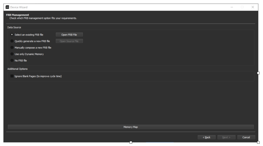
On the FRB management page, there are some options for FRB creation and usage. First, you can choose the source:
• Select an existing FRB file: select an already created FRB file.
• Quickly generate a new FRB file: select an FRB source file and convert it with just a single click. This is the fastest way to convert a source file to FRB. The FRB is created and saved in the standard user data folder with the same filename as the selected source file (some special characters like ‘&’ are not allowed).
• Manually compose a new FRB file: open a new window to access advanced features about FRB file creation. See the chapter “Advanced FRB Manager” for more details.
• Use only Dynamic Memory: this does not create any FRB file; it only uses dynamic memory. See chapter “Serial Numbering.”
• No FRB file: this will set no FRB files.
Communication settings
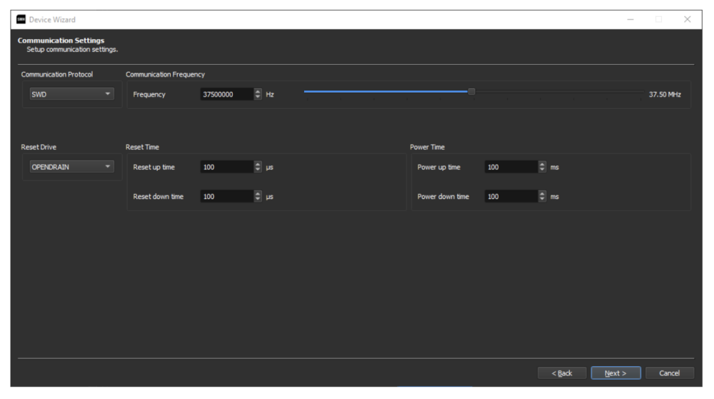
All these settings will enter as #TCSETPAR in the final project.
Powering settings page
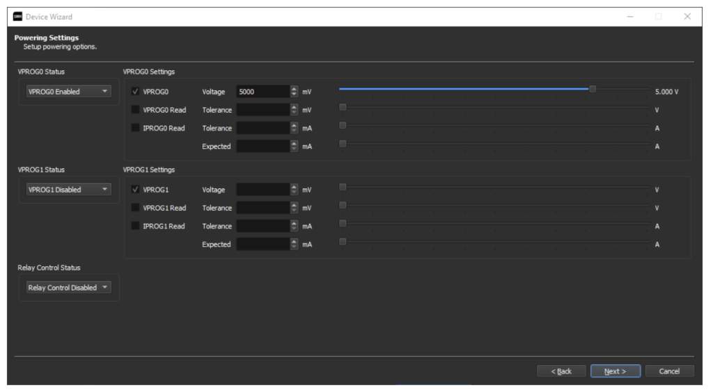
This page allows the user to set the values of VPROG0 and VPROG1 and their tolerance values (#TCSETPAR values). The VPROG0 is also the logical voltage of the DIO signals. VPROG1, instead, can only be used as a power supply. The tolerance for the VPROG and IPROG monitoring can be set. On this page, it is also possible to set the relay barrier usage, to manage automatically the opening and closing of the relays.
Additional commands page
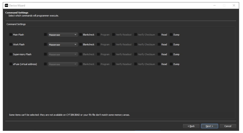
This page contains some additional commands related to the device. This page is driver and device-dependent. To know more about the settings here presented, the WIKI of the driver can be consulted.
This page contains some additional commands related to the device. This page is driver and device-dependent. To know more about the settings here presented, the WIKI of the driver can be consulted.
Add the project to a channel
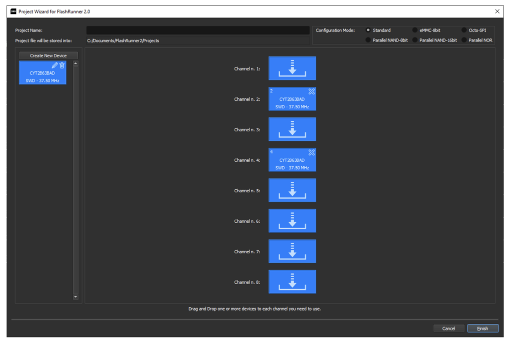
Once the device is created, on the main page the user will see on the left the device. With drag and drop the user can insert the device into the desired channels.
The user can create new devices and add them to a channel. Once the project creation is ended, the user can give a name to the project and click on finish.